Step 6: Install the sub-harness that connects the starter relay to the starter solenoid
Created:
Updated:
Applicable to these part numbers:
PLEASE NOTE:
If you purchased the RELAY-HARNESS, please skip this step. Follow these alternative installation instructions after installing all of the other steps.
Magneti Marelli voltage regulator
- Connect the brown wire from the main harness to terminal 86 on the relay.
- Connect one end the short red wire (unsheathed) to terminal 30 on the relay. This end will have a 6.3 mm female spade terminal.
- Connect the other end of the short red wire (unsheathed) to 51B on the voltage regulator. The end will have a 6 mm ring terminal.
- Route the pair of sheathed wires to the left side of the transmission near the starter. I always route these wires between the battery tray and the rear fender in the little
triangle
space that is available there. I route the wires straight down behind the swing arm member, and then route them forward toward the starter area. - At the relay, connect the black wire to terminal 85 on the relay.
- At the relay, connect the red wire to terminal 87 on the relay.
- At the neutral switch, connect the black wire to the neutral switch. If you connect the wire to the switch, the transmission must be in neutral in order to actuate the starter. I prefer to permanently ground the black wire to one of the bolts that secures the neutral switch to the transmission. The choice is yours.
- At the starter, connect red wire to the starter solenoid.
Bosch voltage regulator
- Connect the brown wire from the main harness to terminal 86 on the relay.
- Connect one end the short red wire (unsheathed) to terminal 30 on the relay. This end will have a 6.3 mm female spade terminal.
- Connect the other end of the short red wire (unsheathed) to 51B on the voltage regulator. The end will have a 9.5 mm female spade terminal.
- Route the pair of sheathed wires to the left side of the transmission near the starter. I always route these wires between the battery tray and the rear fender in the little
triangle
space that is available there. I route the wires straight down behind the swing arm member, and then route them forward toward the starter area. - At the relay, connect the black wire to terminal 85 on the relay.
- At the relay, connect the red wire to terminal 87 on the relay.
- At the neutral switch, connect the black wire to the neutral switch. If you connect the wire to the switch, the transmission must be in neutral in order to actuate the starter. I prefer to permanently ground the black wire to one of the bolts that secures the neutral switch to the transmission. The choice is yours.
- At the starter, connect red wire to the starter solenoid.
Alternator equipped
- Connect the brown wire from the main harness to terminal 86 on the relay.
- Connect one end the short red wire (unsheathed) to terminal 30 on the relay. This end will have a 6.3 mm female spade terminal.
- Connect the other end of the short red wire (unsheathed) to the positive terminal on the battery. The end will have a 6 mm ring terminal.
- Route the pair of sheathed wires to the left side of the transmission near the starter. I always route these wires between the battery tray and the rear fender in the little
triangle
space that is available there. I route the wires straight down behind the swing arm member, and then route them forward toward the starter area. - At the relay, connect the black wire to terminal 85 on the relay.
- At the relay, connect the red wire to terminal 87 on the relay.
- At the neutral switch, connect the black wire to the neutral switch. If you connect the wire to the switch, the transmission must be in neutral in order to actuate the starter. I prefer to permanently ground the black wire to one of the bolts that secures the neutral switch to the transmission. The choice is yours.
- At the starter, connect red wire to the starter solenoid.
Original starter relay: Photos of the connections to the original starter relay
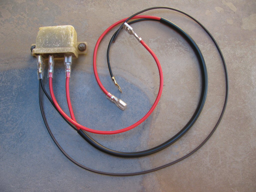
Photo courtesy of Gregory Bender.
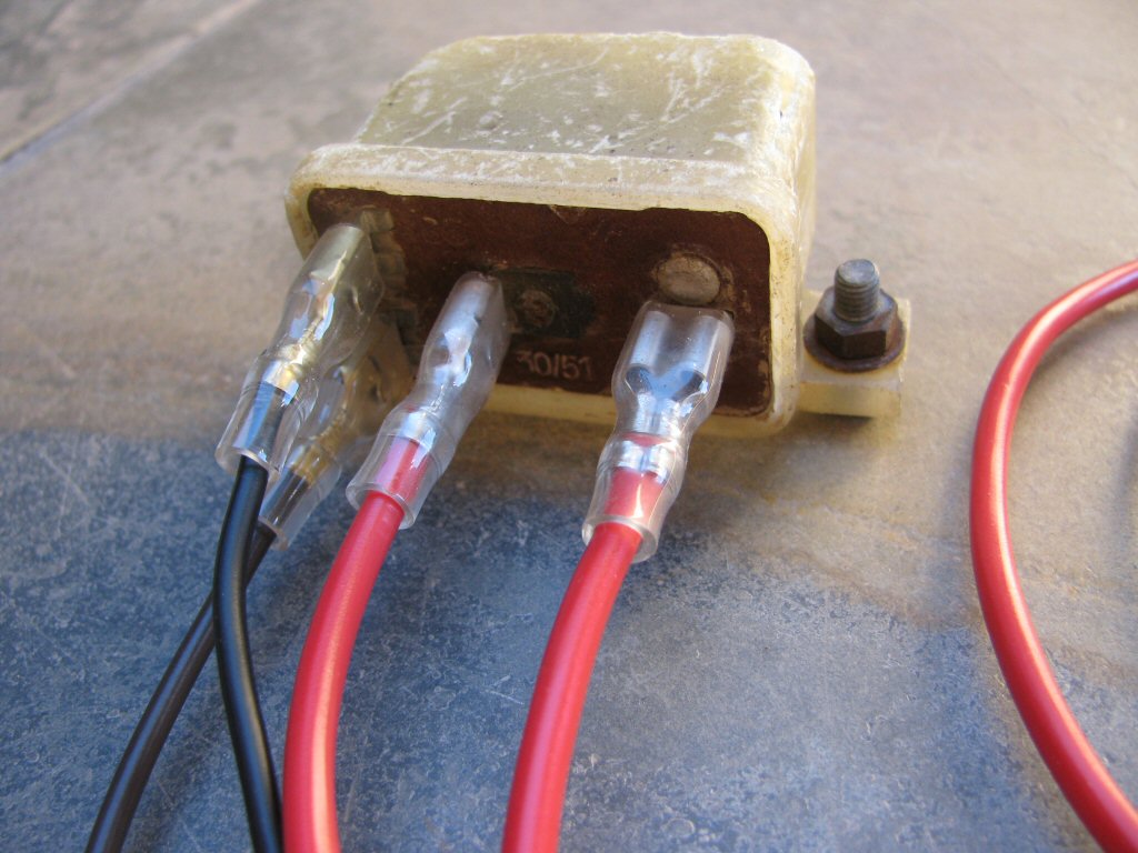
Photo courtesy of Gregory Bender.
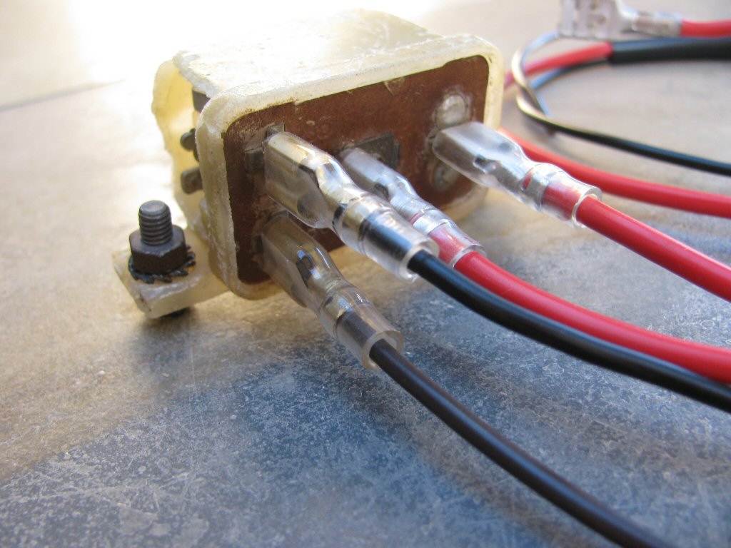
Photo courtesy of Gregory Bender.

Photo courtesy of Gregory Bender.
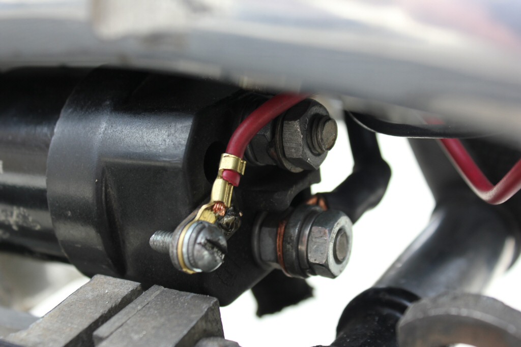
Photo courtesy of Gregory Bender.
Modern starter relays
Please reference the PDF file below for terminal connections with non-original relays.
Starter relay
Pages: 1